This post may contain affiliate links. If you make a purchase through these links, we may earn a commission at no additional cost to you.
Introduction: The World of Metal 3D Printing and Why Choosing Wisely Matters
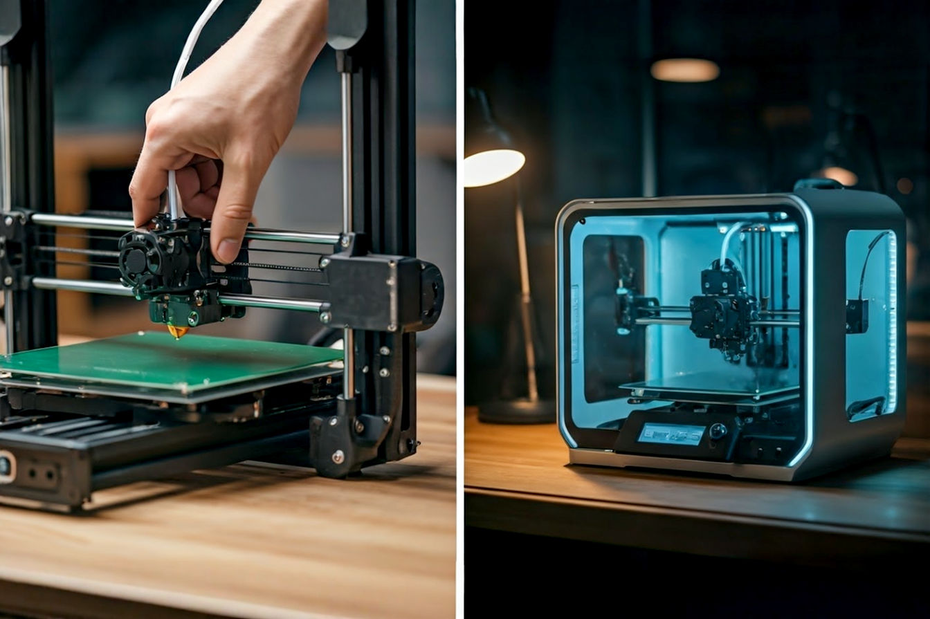
Metal 3D printing, also known as metal additive manufacturing, is revolutionizing how we design and produce metal parts. Instead of traditional methods that cut away material (like machining) or mold it (like casting), 3D printing builds parts layer by layer directly from a digital design. This capability unlocks incredible possibilities, from creating complex geometries that were once impossible to making lighter, stronger components for critical applications.
What is Metal 3D Printing?
At its core, metal 3D printing is a manufacturing process that uses a computer-aided design (CAD) model to guide a machine in depositing and fusing metal material, typically in powder or wire form, layer by layer. Think of it like building a structure with very fine metal dust or wire, where each new layer is precisely placed and joined to the one below it until the final object takes shape. This additive approach minimizes waste compared to subtractive methods and allows for highly intricate internal structures and designs.
Why is Selecting the Right Technology Crucial?
While the term “metal 3D printing” might sound like a single process, it actually encompasses several distinct technologies. Each method works differently, uses different forms of metal material, and has unique strengths and weaknesses. Choosing the right metal printer technology isn’t just about picking a machine; it’s about selecting the process that best aligns with your project’s specific needs. The wrong choice can lead to excessive costs, parts that don’t meet performance requirements, slow production times, or even an inability to manufacture the part at all. Understanding the nuances of each technology is the first step toward making an informed decision that ensures your project’s success.
Overview of the Article’s Structure
This article will serve as your comprehensive guide to navigating the world of metal 3D printing technologies. We’ll break down the main types of metal printers, explain how they work in both simple and technical terms, discuss their pros and cons, and highlight their typical applications. More importantly, we’ll provide a detailed look at the key factors you need to consider when evaluating these options, from material properties and part geometry to cost and post-processing. By the end, you’ll have a solid framework for choosing the metal additive manufacturing technology that’s the perfect fit for your unique project requirements.
Understanding the Main Metal 3D Printing Technologies
Metal 3D printing technologies can be broadly categorized by how they apply and fuse the metal material. Let’s dive into the most common methods you’ll encounter.
Powder Bed Fusion (PBF)
Powder Bed Fusion is one of the most established and widely used categories of metal 3D printing. These processes work by spreading a thin layer of fine metal powder across a build platform. Then, a high-energy source selectively melts or fuses the powder particles together based on the design data. This process is repeated layer by layer until the part is complete, embedded within the unfused powder bed.
Selective Laser Melting (SLM) and Direct Metal Laser Sintering (DMLS)
These two terms are often used interchangeably, and their processes are very similar. Both use a laser as the energy source to fuse metal powder. The main difference is often described in the result: SLM typically achieves full melting of the powder particles, creating a fully dense, homogenous metal part. DMLS, while also using a laser, might involve sintering (fusing particles without full melting) or partial melting, which can sometimes result in parts with slightly higher porosity if not optimized. However, modern DMLS systems often achieve densities comparable to SLM. For simplicity, we’ll often refer to them together or primarily use SLM as it represents the goal of full density.
How SLM/DMLS Works (Simplified)
Imagine you have a flat tray filled with very fine metal dust. A roller spreads a super-thin layer of this dust. Then, a powerful laser beam shines onto the dust, drawing the shape of the first slice of your part. Everywhere the laser hits, the metal dust melts and fuses together. After the laser finishes the slice, the tray moves down just a tiny bit, a new layer of dust is spread on top, and the laser draws the next slice, fusing it to the layer below. This repeats until your whole part is built, buried in the leftover dust.
How SLM/DMLS Works (Technical Detail)
SLM and DMLS systems operate within a sealed chamber, typically filled with an inert gas like argon or nitrogen to prevent oxidation of the reactive metal powders at high temperatures. The process begins with a powder dispensing system spreading a layer of metal powder, usually 20-60 micrometers thick, onto a build platform. A high-power laser (often fiber or Ytterbium lasers, ranging from 100W to over 1000W) is directed by a system of mirrors (galvanometers) across the powder bed. The laser beam selectively scans the cross-section of the part according to the CAD data. The energy from the laser raises the temperature of the powder particles to their melting point (or near-melting point for sintering), causing them to coalesce and form a solid layer. The build platform then lowers by one layer thickness, a new layer of powder is applied, and the process repeats. Unmelted powder remains in place, supporting overhanging features of the part during the build.
Key Characteristics of SLM/DMLS
SLM/DMLS is known for producing parts with high density (often >99.5%), excellent mechanical properties that can be comparable to or even exceed wrought materials, and the ability to create complex geometries with fine details and thin walls. The parts are built with minimal porosity, which is crucial for structural integrity.
Typical Materials Used in SLM/DMLS
A wide range of metal alloys can be processed using SLM/DMLS, provided they can be atomized into fine, spherical powders and are weldable. Common materials include:
- Stainless Steels: 316L, 17-4 PH
- Aluminum Alloys: AlSi10Mg
- Titanium Alloys: Ti6Al4V (Grade 5 and Grade 23)
- Nickel Alloys: Inconel 625, Inconel 718
- Cobalt-Chrome Alloys
- Tool Steels
- Precious Metals
Pros of SLM/DMLS
- High Density and Strength: Produces parts with material properties close to wrought metals.
- Excellent Resolution and Detail: Capable of building intricate features and thin walls.
- Wide Material Selection: Compatible with many common engineering alloys.
- Good Surface Finish (relative to some other AM methods): While still requiring post-processing, the as-built surface is often smoother than DED or WAAM.
Cons of SLM/DMLS
- Support Structures Required: Overhanging features need support structures built from the same metal powder, which must be removed later.
- Internal Stress: The rapid heating and cooling can induce significant residual stress in parts, often requiring heat treatment (like stress relief) post-build.
- Relatively Slow Build Speed: Building layer by layer with a single laser can be time-consuming, especially for large parts. Multi-laser systems help mitigate this.
- Expensive Equipment and Materials: SLM/DMLS machines and the fine metal powders they use are costly.
- Part Size Limitations: The size of parts is limited by the dimensions of the machine’s build chamber.
Common Applications for SLM/DMLS
SLM/DMLS is widely used in demanding industries where high performance and complex geometries are critical. This includes:
- Aerospace: Lightweight structural components, turbine blades, fuel nozzles.
- Medical: Custom orthopedic implants (hips, knees), dental prosthetics, surgical instruments.
- Automotive: Lightweight components, complex cooling channels in molds, prototyping.
- Tooling: Conformal cooling channels in injection molds and dies.
- Industrial: Prototypes, small-batch production of complex parts.
Electron Beam Melting (EBM)
Electron Beam Melting is another Powder Bed Fusion technology, but instead of a laser, it uses a high-power electron beam to fuse the metal powder. EBM operates in a vacuum environment, which is advantageous for processing reactive metals like titanium and certain nickel alloys.
How EBM Works (Simplified)
Think of the same tray of metal dust as with SLM, but this time, instead of a laser pointer, you’re using a controlled beam of electrons, like in an old TV screen, but much more powerful. This electron beam scans across the metal dust, melting and fusing it layer by layer. The whole process happens inside a vacuum chamber to keep the metal clean.
How EBM Works (Technical Detail)
EBM systems operate under a high vacuum (typically 10−4 to 10−6 mbar). An electron emitter (electron gun) generates a beam of electrons, which is then accelerated and focused using magnetic coils. The beam is directed by deflection coils across the powder bed. Unlike SLM/DMLS which often uses a single pass per area, EBM typically uses a technique called “pre-sintering” or “pre-heating” where the electron beam quickly scans the entire powder layer before the main melting pass. This pre-heating keeps the powder bed at an elevated temperature (often 500-1000°C), which helps reduce residual stress in the part and makes the powder slightly conductive, preventing charge build-up from the electron beam. The main melting pass then selectively fuses the powder. The build platform lowers, and a new layer of powder is raked or dispensed on top.
Key Characteristics of EBM
EBM is known for building parts in a vacuum environment, which is ideal for reactive metals. The high build temperature reduces residual stress compared to SLM/DMLS. EBM typically has a faster build speed than single-laser SLM/DMLS due to the electron beam’s ability to scan multiple melt pools simultaneously and the pre-heating step. However, it generally results in a rougher surface finish and slightly lower resolution than SLM/DMLS.
Typical Materials Used in EBM
EBM is particularly well-suited for processing materials that benefit from a vacuum environment or higher process temperatures. Common materials include:
- Titanium Alloys: Ti6Al4V
- Nickel Alloys: Inconel 718, Inconel 738
- Cobalt-Chrome Alloys
- Niobium
Pros of EBM
- Low Residual Stress: The high build temperature minimizes stress accumulation, reducing the need for extensive post-build heat treatment.
- Good for Reactive Metals: Vacuum environment prevents oxidation.
- Faster Build Speed (often): Electron beam can melt larger areas or multiple spots simultaneously.
- Good Material Properties: Produces fully dense parts with excellent mechanical properties.
Cons of EBM
- Rougher Surface Finish: Parts typically require more post-processing to achieve a smooth surface.
- Lower Resolution: Generally less capable of producing extremely fine features compared to SLM/DMLS.
- Requires Vacuum: The vacuum environment adds complexity and cost to the machine and process.
- Support Structures Still Needed: Although sometimes less extensive than SLM/DMLS due to the pre-heating.
- Limited Material Range (compared to SLM): Primarily focused on high-temperature and reactive alloys.
Common Applications for EBM
EBM is a preferred technology for applications requiring high-performance parts from specific alloys, particularly in:
- Aerospace: Turbine components, structural parts, brackets (especially in titanium).
- Medical: Orthopedic implants (hips, knees, spine) made from titanium and cobalt-chrome.
- Motorsport: Lightweight, high-strength components.
Binder Jetting
Binder Jetting is a metal 3D printing process that works very differently from Powder Bed Fusion. Instead of using heat to fuse powder particles, it uses a liquid binding agent to glue them together layer by layer in a powder bed. The resulting “green” part is fragile and requires significant post-processing, including a crucial sintering step in a furnace to achieve final density and strength.
How Binder Jetting Works (Simplified)
Imagine you have a tray of metal dust, like with PBF. A roller spreads a thin layer. But this time, instead of a laser, a print head (like in an inkjet paper printer) moves across the dust and squirts tiny drops of a liquid glue in the shape of your part’s slice. This glues the dust particles together in that spot. The tray moves down, a new layer of dust is spread, and the print head glues the next slice. You end up with a part made of metal dust held together by glue. This fragile part then goes into a hot oven (a furnace) where the glue burns away, and the metal particles fuse together into a solid metal object.
How Binder Jetting Works (Technical Detail)
Binder Jetting involves spreading a layer of metal powder onto a build platform. A print head, similar to those used in 2D inkjet printers, selectively deposits droplets of a liquid binder onto the powder bed according to the digital model. The binder acts as a glue, adhering the powder particles together in the desired shape. After each layer is printed, the build platform lowers, and a new layer of powder is spread. This process is repeated until the entire part is formed within the powder bed. The resulting part, called a “green” part, is held together by the binder and is very fragile.
The green part is then removed from the loose powder (a process called “de-powdering”). Following de-powdering, the part undergoes a crucial post-processing sequence. First, it’s typically cured or dried to strengthen the binder. Then, it goes through a debinding step, where the binder is removed, often thermally or chemically. Finally, the part is sintered in a high-temperature furnace. During sintering, the metal particles fuse together through solid-state diffusion, consolidating the part and achieving its final density and mechanical properties. The part shrinks significantly during sintering (typically 15-25%), and this shrinkage must be accounted for in the initial design.
Key Characteristics of Binder Jetting
Binder Jetting is known for its high build speed and scalability due to the print head’s ability to cover the powder bed quickly. It can build multiple parts simultaneously across the build platform. It also doesn’t require support structures for thermal reasons (as there’s no melting during printing), although powder support is inherent. It’s often more cost-effective for higher volume production compared to PBF. However, the parts require significant post-processing, including debinding and sintering, which adds time and complexity. The final parts typically have lower density and mechanical properties compared to PBF parts, and the surface finish is usually rougher.
Typical Materials Used in Binder Jetting
Binder Jetting is compatible with a wide range of metal powders, including materials that are difficult to process with PBF because they don’t weld well. Common materials include:
- Stainless Steels: 17-4 PH, 316L
- Low Alloy Steels
- Tool Steels
- Nickel Alloys
- Cobalt-Chrome
- Copper
- Ceramics (though not metal, the process is similar)
Pros of Binder Jetting
- High Build Speed and Throughput: Can produce parts much faster than PBF technologies.
- Scalability: Well-suited for larger build volumes and higher production quantities.
- No Thermal Support Structures: Simplifies design and post-processing compared to PBF.
- Lower Equipment Cost (often): Machines can be less expensive than PBF systems.
- Wider Material Compatibility (in some cases): Can process materials difficult to weld.
Cons of Binder Jetting
- Significant Post-processing Required: Debinding and sintering are complex, time-consuming, and critical steps.
- Part Shrinkage: Parts shrink substantially and predictably during sintering, requiring design compensation.
- Lower Density and Mechanical Properties: Final properties are highly dependent on the sintering process and may not match wrought materials.
- Rougher Surface Finish: Requires more finishing steps to achieve desired smoothness.
- Fragile Green Parts: Handling the parts before sintering requires care.
Common Applications for Binder Jetting
Binder Jetting is gaining traction for applications where speed, volume, and cost-effectiveness are key, and where the final material properties achieved through sintering are acceptable. This includes:
- Automotive: Prototyping, complex powertrain components, tooling inserts.
- Consumer Goods: Small metal parts, decorative items.
- Industrial: Low-cost production of complex parts, tooling.
- Education and Research: Exploring new materials and applications.
Directed Energy Deposition (DED)
Directed Energy Deposition (DED) processes build parts by melting material as it’s being deposited onto a substrate or a previously built layer. A concentrated energy source (usually a laser or electron beam) creates a melt pool on the surface, and metal material (either powder or wire) is fed into this melt pool simultaneously. The material solidifies rapidly as the energy source moves, building up the part layer by layer or bead by bead.
How DED Works (Simplified)
Imagine you’re welding, but instead of just joining two pieces, you’re building a new shape from scratch. A nozzle blows metal powder or feeds metal wire onto a spot where a powerful laser or electron beam is creating a tiny pool of melted metal. As the nozzle and energy source move, the melted metal cools and hardens, adding a small line or bead of material. You repeat this process, laying down beads next to and on top of each other, until your part is built.
How DED Works (Technical Detail)
DED systems typically consist of a multi-axis robotic arm or gantry system with a deposition head. The head contains the energy source (laser, electron beam, or even plasma arc) and one or more nozzles for feeding the metal material. Material can be fed as powder (blown coaxially or sideways into the melt pool) or as wire. The energy source creates a melt pool on the substrate or the previous layer. The fed material melts within this pool and fuses to the underlying material. As the head moves, the melt pool solidifies, forming a solid track or bead. The process is repeated to build up layers. DED can operate in an open environment (with shielding gas), a vacuum, or an inert atmosphere, depending on the material and energy source.
Key Characteristics of DED
DED is characterized by its ability to build large parts, repair existing components, and deposit material onto existing structures. It generally has a higher deposition rate (build speed in terms of volume per hour) than PBF, making it suitable for larger, less complex parts or for adding features to existing objects. However, DED typically results in lower resolution and a rougher surface finish than PBF. The material properties can be anisotropic (varying depending on direction) due to the bead-by-bead deposition.
Variations of DED (Wire-based like WAAM, Powder-based like LENS)
There are several variations of DED, primarily differing in the energy source and material feedstock:
- Laser-based DED (e.g., LENS – Laser Engineered Net Shaping): Uses a laser and metal powder feedstock. Offers relatively good control and material flexibility.
- Electron Beam DED: Uses an electron beam and powder or wire feedstock. Operates in a vacuum, good for reactive metals.
- Plasma Arc DED: Uses a plasma arc and wire feedstock. Often referred to as Wire Arc Additive Manufacturing (WAAM). Known for very high deposition rates and suitability for large structures, often using welding equipment.
Typical Materials Used in DED
DED can process a wide variety of weldable metals, often using standard welding wire or readily available powders. Common materials include:
- Titanium Alloys
- Nickel Alloys
- Stainless Steels
- Aluminum Alloys
- Cobalt Alloys
- Tool Steels
Pros of DED
- Ability to Build Large Parts: Not limited by a build chamber size in the same way PBF is.
- High Deposition Rates: Faster for building large volumes of material.
- Repair and Feature Addition: Can repair damaged metal parts or add material to existing structures.
- Material Flexibility: Can often use standard welding wires or less expensive powders.
Cons of DED
- Lower Resolution and Accuracy: Less suited for parts with fine details or complex internal features.
- Rough Surface Finish: Requires significant post-processing (often machining) to achieve final dimensions and surface quality.
- Anisotropic Properties: Mechanical properties can vary depending on the build direction.
- Requires Support Structures (often): Though sometimes less complex than PBF supports.
Common Applications for DED
DED is frequently used in heavy industries and for applications requiring large parts or repair capabilities:
- Aerospace: Repairing turbine blades, structural components.
- Oil & Gas: Repairing drill bits, valves.
- Heavy Industry: Large structural components, tooling repair.
- Defense: Repair and manufacturing of large metal parts.
Material Extrusion (Bound Metal Deposition)
Metal Material Extrusion, sometimes called Bound Metal Deposition (BMD) or Fused Filament Fabrication (FFF) for metal, adapts plastic extrusion 3D printing technology for metals. It uses a filament made of metal powder bound together with polymer or wax binders. This filament is extruded through a heated nozzle, building the part layer by layer. Like Binder Jetting, the resulting “green” part requires debinding and sintering.
How Material Extrusion for Metal Works (Simplified)
Think of a regular desktop 3D printer that makes plastic objects, but instead of a plastic string, it uses a special string that’s mostly metal powder mixed with a bit of plastic glue. The printer melts the plastic glue just enough so it can squeeze the metal-filled goo out of a nozzle, drawing the shape of the first layer. This goo hardens as it cools. Layer after layer is built this way. The resulting part feels like plastic but is heavy with metal powder. Then, like with Binder Jetting, this part goes through steps to remove the plastic glue and then into a furnace to fuse the metal powder into a solid metal part.
How Material Extrusion for Metal Works (Technical Detail)
Metal Material Extrusion uses feedstock in the form of a filament or rod, which consists of metal powder (typically 50-97% by volume) uniformly dispersed within a polymer or wax binder matrix. This filament is fed into a heated print head, where the binder softens, allowing the “ink” (metal powder and binder) to be extruded through a nozzle. The material is deposited onto a build platform, and subsequent layers are built on top. The binder provides structural integrity to the “green” part.
After printing, the part undergoes post-processing. First, a debinding step removes most of the binder. This can be done chemically (e.g., by dissolving the polymer binder in a solvent) or thermally (by heating the part to evaporate the binder). After debinding, the part is sintered in a furnace at a high temperature, below the metal’s melting point. During sintering, the metal particles consolidate, the remaining binder burns off, and the part densifies and shrinks significantly (again, requiring design compensation).
Key Characteristics of Metal Material Extrusion
This technology is often seen as a more accessible and office-friendly method of metal 3D printing compared to PBF or DED, with lower equipment costs. It can produce parts with good feature resolution relative to DED or Binder Jetting (before sintering). However, it also requires significant post-processing (debinding and sintering), which adds complexity and can affect final part properties. The final parts typically have lower density and mechanical properties than PBF parts and can exhibit some porosity.
Typical Materials Used in Metal Material Extrusion
The material range is growing, often available in proprietary filament cartridges. Common materials include:
- Stainless Steels: 17-4 PH, 316L
- Tool Steels
- Nickel Alloys
- Copper
Pros of Metal Material Extrusion
- Lower Equipment Cost: Often the most affordable entry point into metal 3D printing.
- Office-Friendly: Machines are generally safer and easier to operate than powder-bed systems.
- Good Feature Resolution (Green State): Can produce parts with fine details before sintering.
- Minimal Material Waste: Uses filament, reducing powder handling issues.
Cons of Metal Material Extrusion
- Significant Post-processing Required: Debinding and sintering are essential and complex steps.
- Part Shrinkage: Substantial and predictable shrinkage occurs during sintering.
- Lower Density and Mechanical Properties: Final part quality may not match PBF.
- Slower Build Speed (often): Extrusion speed can be a limiting factor.
- Material Properties Can Be Anisotropic: Due to the layered deposition.
Common Applications for Metal Material Extrusion
This technology is well-suited for prototyping, tooling, and producing small-to-medium sized functional parts where cost and accessibility are primary drivers, and the final material properties are sufficient.
- Prototyping: Creating functional metal prototypes quickly and relatively inexpensively.
- Tooling: Jigs, fixtures, soft jaws.
- Educational: Introducing metal 3D printing concepts.
- Small Functional Parts: Brackets, connectors, replacement parts.
Key Factors to Consider When Choosing a Metal Printer Technology
Now that we’ve covered the main technologies, how do you decide which one is right for your project? It requires carefully evaluating your specific needs against the capabilities and limitations of each method. Here are the critical factors to consider:
Application Requirements and Functional Needs
The most important starting point is understanding what the final part needs to do.
What Will the Part Be Used For?
Is it a structural component under high stress? A medical implant needing biocompatibility? A lightweight part for aerospace? A decorative item? The intended function dictates the necessary material properties, required accuracy, and acceptable surface finish. A critical aerospace part will have vastly different requirements than a simple prototype or a piece of tooling.
Industry-Specific Standards and Regulations
Many industries, like aerospace, medical, and automotive, have strict standards and regulations regarding material properties, manufacturing processes, and part qualification. Ensure the chosen technology and material can meet these specific requirements (e.g., FAA regulations for aerospace parts, FDA approval for medical implants). Some technologies have more established track records and certifications in certain industries than others.
Material Properties Required
The mechanical, thermal, and chemical properties the final part must possess are paramount.
Strength, Hardness, Corrosion Resistance, Temperature Resistance
Does the part need to withstand high loads (tensile strength, yield strength)? Resist wear (hardness)? Operate in harsh chemical environments (corrosion resistance)? Maintain integrity at high or low temperatures? Different metal alloys offer different combinations of these properties. You must select an alloy that meets your needs, and then choose a 3D printing technology that is compatible with that alloy and can achieve the required material properties through its process and subsequent heat treatments. For example, if you need high strength and temperature resistance for a turbine component, nickel alloys processed with SLM or EBM might be suitable. If you need biocompatibility for an implant, titanium with SLM or EBM is a common choice.
Material Availability for Each Technology
Not all metal alloys are available for every 3D printing technology. PBF generally has the widest range of high-performance alloys in powder form. Binder Jetting and Material Extrusion are expanding their material libraries but might not offer the same exotic or high-strength alloys as PBF or DED. DED often uses standard welding wires or readily available powders. Verify that your required material is compatible and available for the technologies you’re considering.
Part Geometry and Complexity
The shape and features of your part play a significant role in determining which technology is feasible and efficient.
Intricate Designs, Internal Channels, Overhangs
Does your part have complex internal cooling channels, lightweight lattice structures, or delicate features? PBF technologies (SLM/DMLS, EBM) generally excel at producing highly complex geometries with fine details and intricate internal features due to the support provided by the surrounding powder bed. Binder Jetting also handles complexity well as it doesn’t require thermal supports, but resolution is lower. DED and Metal Material Extrusion are typically less suited for very fine details or complex internal structures due to their deposition methods and resolution limitations.
Minimum Feature Size and Wall Thickness
How small are the smallest details on your part? What is the minimum required wall thickness? SLM/DMLS generally offers the best resolution and capability for thin walls and fine features (down to tens of micrometers). EBM has slightly lower resolution. Binder Jetting and Metal Material Extrusion have coarser resolution in the green state, and the sintering process can affect final feature size and tolerance. DED has the lowest resolution and is best for larger features.
Required Accuracy and Surface Finish
The dimensional precision and surface quality needed for your part are critical considerations.
Dimensional Tolerances
How precise do the dimensions of your final part need to be? PBF technologies (SLM/DMLS, EBM) generally offer the best as-built dimensional accuracy among metal AM processes, often achieving tolerances in the range of ±0.1–0.2% of dimension, with a minimum deviation. However, post-processing (like machining) is almost always required to meet tight tolerances on critical features. Binder Jetting and Material Extrusion have lower as-built accuracy, and the significant shrinkage during sintering requires careful compensation in the design and process control. DED has the lowest as-built accuracy and typically requires substantial machining to achieve final dimensions.
Surface Roughness and Post-processing Needs
What level of surface smoothness does your part require? As-built metal 3D printed parts generally have a rough surface finish (often Ra values in the 10-20 µm range or higher, depending on the technology). SLM/DMLS typically produces smoother surfaces than EBM, DED, or Binder Jetting. If a very smooth surface is needed (e.g., for aerodynamic flow, medical implants, or mating surfaces), significant post-processing like bead blasting, grinding, machining, or polishing will be necessary, adding cost and time.
Production Volume and Speed
How many parts do you need, and how quickly do you need them?
Prototyping vs. Batch Production vs. Mass Production
Are you making a single prototype, a small batch of parts, or planning for high-volume manufacturing? For single prototypes or small batches requiring high performance and complexity, PBF (SLM/DMLS, EBM) is often suitable despite its slower speed per part. For higher volumes, Binder Jetting’s speed and scalability, despite requiring extensive post-processing, can make it more cost-effective. Metal Material Extrusion is good for accessible prototyping and small batch tooling. DED is best for large, low-volume parts or repairs.
Build Speed and Throughput of Different Technologies
Consider the actual time it takes to produce a finished part, including printing time and post-processing time. Binder Jetting often has the fastest build time in the printer due to the print head’s speed and ability to print multiple parts across a large bed, but the debinding and sintering steps add considerable time. PBF is slower in the printer but results in parts closer to final properties, reducing some post-processing time (though heat treatment is common). DED is fast for adding volume but slow for detailed parts. Material Extrusion printing is relatively slow, and post-processing adds significant time.
Cost Analysis: Beyond the Machine Price
Evaluating cost requires looking at the total cost of ownership and the cost per part, not just the initial machine investment.
Machine Purchase and Maintenance Costs
Metal 3D printers, especially PBF and high-end DED systems, are expensive capital investments. Binder Jetting and Material Extrusion machines tend to have lower entry costs. Factor in ongoing maintenance, service contracts, and potential upgrades.
Material Costs
Metal powders for PBF are typically the most expensive feedstock. Powders for Binder Jetting and DED can be less costly, especially if using standard welding grades. Metal Material Extrusion filaments also have a cost per kilogram. Consider material yield (how much powder is wasted vs. used in the part) and the cost of inert gases (for PBF and some DED).
Post-processing Costs
This is often the most underestimated cost factor. Support removal, heat treatments (stress relief, HIP – Hot Isostatic Pressing), debinding, sintering, machining, grinding, and polishing all add significant labor, equipment, and time costs. Technologies requiring more extensive post-processing (Binder Jetting, Material Extrusion, DED) will have higher post-processing costs per part. PBF parts also require post-processing, but often less extensive machining than DED.
Labor and Operational Costs
Factor in the cost of skilled operators needed to run the machines, handle powders safely, perform post-processing steps, and maintain equipment. Energy consumption can also be significant, especially for high-temperature processes.
Post-processing Requirements and Their Impact
As highlighted, post-processing is integral to metal 3D printing and heavily influences the final part’s properties, cost, and lead time.
Support Removal
PBF and some DED processes require support structures to anchor the part to the build plate and support overhanging features during the high-temperature build. Removing these supports can be labor-intensive and challenging, especially for complex internal geometries. Binder Jetting and Material Extrusion require minimal or no thermal supports, simplifying this step, but require debinding and sintering instead.
Heat Treatment (Stress Relief, HIP)
Parts built with processes involving high thermal gradients (like PBF and DED) often accumulate significant residual stress. Heat treatments like stress relief are commonly performed to alleviate this stress and prevent part distortion or cracking. Hot Isostatic Pressing (HIP) is another post-processing step sometimes used for PBF parts to reduce internal porosity and improve mechanical properties, particularly for critical applications.
Machining, Grinding, Polishing
Unless your required tolerances and surface finish are very loose, some level of machining, grinding, or polishing will likely be needed to achieve final dimensions, smooth surfaces, or create critical mating features. DED parts almost always require significant machining. PBF parts often require machining on critical interfaces. Binder Jetting and Material Extrusion parts, after sintering, also typically need machining for tight tolerances.
Debinding and Sintering (for Binder Jetting and Material Extrusion)
These are multi-step, critical processes unique to Binder Jetting and Material Extrusion. Debinding removes the binder, and sintering fuses the metal particles. These steps require specialized equipment (furnaces, chemical baths) and careful process control to achieve the desired density, dimensions (accounting for shrinkage), and material properties.
Safety Considerations and Facility Requirements
Operating metal 3D printers involves handling fine metal powders, high-power energy sources, and sometimes inert gases or vacuum.
Handling Metal Powders
Many fine metal powders are combustible or even explosive when dispersed in air (e.g., aluminum, titanium). Handling requires strict safety protocols, including proper ventilation, grounding, personal protective equipment (PPE), and potentially specialized facilities to mitigate risks. PBF and Binder Jetting systems work with powder beds, requiring careful handling during machine operation and powder removal.
High-Power Lasers or Electron Beams
PBF and some DED systems use high-power lasers or electron beams that pose significant safety risks if not properly contained and operated. Machines have safety interlocks and enclosures, but facility requirements might include eye protection zones or specific electrical hookups.
Inert Gas Environments
PBF processes often use inert gases (argon, nitrogen) to prevent oxidation. This requires gas supply infrastructure and ventilation to prevent gas buildup. EBM operates in a vacuum, requiring robust vacuum pumps and systems.
Ventilation and Filtration
Proper ventilation and air filtration are essential to manage fine airborne particles (metal powder, fumes) generated during printing and post-processing.
Comparing the Technologies: A Decision Framework
Choosing the right technology involves weighing the factors discussed above. There’s no single “best” technology; the optimal choice is always project-dependent.
Technology Comparison Summary
Here’s a simplified comparison across key factors:
| Feature | SLM/DMLS (PBF) | EBM (PBF) | Binder Jetting | DED | Material Extrusion |
| Density/Strength | High, near wrought | High, near wrought | Moderate (post-sintering) | Moderate (can be anisotropic) | Moderate (post-sintering) |
| Resolution/Detail | Excellent | Good | Moderate (Green), Fair (Sintered) | Low | Good (Green), Fair (Sintered) |
| Surface Finish | Good (as-built), requires finishing | Rougher, requires finishing | Rough, requires significant finishing | Very Rough, requires machining | Rough, requires significant finishing |
| Build Speed | Moderate (per part), depends on lasers | Faster (often) | Very Fast (in printer) | Very Fast (deposition rate) | Slow (in printer) |
| Part Size | Limited by chamber | Limited by chamber | Can be larger than PBF | Very Large | Moderate |
| Material Cost | High (Fine Powder) | High (Fine Powder) | Moderate (Powder) | Moderate (Powder/Wire) | Moderate (Filament) |
| Equipment Cost | High | High | Moderate to High | High | Low |
| Post-processing | Supports, Heat Treat, Machining | Supports, Less Heat Treat, Machining | Debind, Sinter, Finishing | Machining, Finishing | Debind, Sinter, Finishing |
| Complexity | High (Machine/Process) | High (Machine/Process) | Moderate (Post-processing) | Moderate (Operation) | Moderate (Post-processing) |
| Safety | Powder, Laser, Gas | Powder, E-Beam, Vacuum | Powder, Binder | Powder/Wire, Energy Source | Binder, Furnace |
| Ideal Use Case | High-perf, complex, critical parts | Reactive metals, low stress | Volume production, lower cost | Large parts, repair | Prototyping, tooling, accessible |
A Step-by-Step Guide to Making Your Choice
Follow these steps to systematically evaluate your options:
Step 1: Define Your Application and Requirements
Clearly articulate the function of the part, the industry it belongs to, and any specific standards or regulations it must meet. What are the non-negotiable performance criteria?
Step 2: Identify Necessary Material Properties
Determine the critical material properties (strength, hardness, temperature resistance, etc.) the part needs to withstand its intended use. This will narrow down the possible metal alloys.
Step 3: Analyze Part Geometry and Size Constraints
Look at the design. Does it have fine features, thin walls, or complex internal channels? What are the overall dimensions of the part? This helps rule out technologies that can’t achieve the required resolution or build size.
Step 4: Determine Accuracy and Surface Finish Needs
How tight are the dimensional tolerances? What level of surface smoothness is required? Be realistic about as-built capabilities and the amount of post-processing you are willing to undertake.
Step 5: Estimate Production Volume and Speed Requirements
How many parts do you need in total, and what is the required lead time? This helps evaluate the throughput and scalability of each technology.
Step 6: Evaluate Total Cost of Ownership
Look beyond the machine price. Factor in material costs, post-processing costs, labor, facility needs, and maintenance. Get quotes for producing your specific part using different technologies.
Step 7: Consider Post-processing and Facility Needs
Assess the complexity and cost of the required post-processing steps for each technology. Do you have the necessary equipment and expertise in-house, or will you need external services? What are the safety and facility implications?
Step 8: Narrow Down and Evaluate Specific Machines
Based on the above factors, you should be able to narrow down to one or two most suitable technologies. Then, research specific machine models within those categories, comparing their build volumes, features, material compatibility, and vendor support.
Case Studies or Examples (Brief Mentions)
Looking at real-world examples can illustrate where each technology shines:
How Aerospace Uses EBM for Titanium
Aerospace companies frequently use EBM for producing complex, lightweight turbine blades and structural components from titanium alloys. The vacuum environment is ideal for processing titanium, and the high build temperature helps minimize residual stress in these critical parts, reducing the need for extensive post-build heat treatment and ensuring structural integrity.
How Medical Devices Use SLM for Implants
SLM is a go-to technology for manufacturing custom orthopedic and dental implants, often from titanium or cobalt-chrome alloys. Its ability to create highly intricate lattice structures (for bone ingrowth) and achieve high density and biocompatibility makes it ideal for these life-critical applications. The precision of SLM allows for patient-specific designs.
How Automotive Uses Binder Jetting for Prototypes or Tooling
Automotive manufacturers are exploring Binder Jetting for faster, more cost-effective production of prototypes and tooling components like complex inserts for casting or injection molding. While not always used for final production parts due to density requirements, its speed makes it valuable for rapid iteration and tooling development.
The Future of Metal 3D Printing Technologies
The field of metal additive manufacturing is constantly evolving.
Advancements and Emerging Trends
We’re seeing advancements in build speed (e.g., multi-laser PBF systems, faster print heads for Binder Jetting), larger build volumes, improved process monitoring and control, and the development of new printable metal alloys. Hybrid systems combining additive and subtractive manufacturing are also becoming more common.
Increasing Accessibility and Applications
As the technologies mature and costs potentially decrease, metal 3D printing is becoming more accessible to a wider range of industries and businesses, moving beyond just high-end aerospace and medical applications. This will drive innovation and expand the possibilities for metal part production.
Conclusion: Making an Informed Decision
Choosing the right metal printer technology for your project is a critical decision that impacts part performance, cost, and production efficiency. It requires a thorough understanding of the different available technologies – Powder Bed Fusion (SLM/DMLS, EBM), Binder Jetting, Directed Energy Deposition (DED), and Material Extrusion – and a careful evaluation of your project’s specific needs.
Recap of Key Considerations
Remember to carefully consider your application’s functional requirements, the necessary material properties, the complexity and size of your part, the required accuracy and surface finish, your production volume and speed needs, the total cost of ownership (including significant post-processing costs), and the safety and facility implications of each technology.
The Importance of Expert Consultation
Navigating these complexities can be challenging. Don’t hesitate to consult with experts in metal additive manufacturing, service bureaus, or technology vendors. They can provide valuable insights, help you evaluate test prints, and guide you toward the technology and process parameters that will best ensure your project’s success. By taking a systematic and informed approach, you can harness the power of metal 3D printing to create innovative, high-performance metal parts.